
Electroplating
Electroplating deposits a metal layer on a prepared component. For hardware, it can provide the specified colour and lustre while contributing to wear and/or corrosion performance when the complete system is defined correctly.
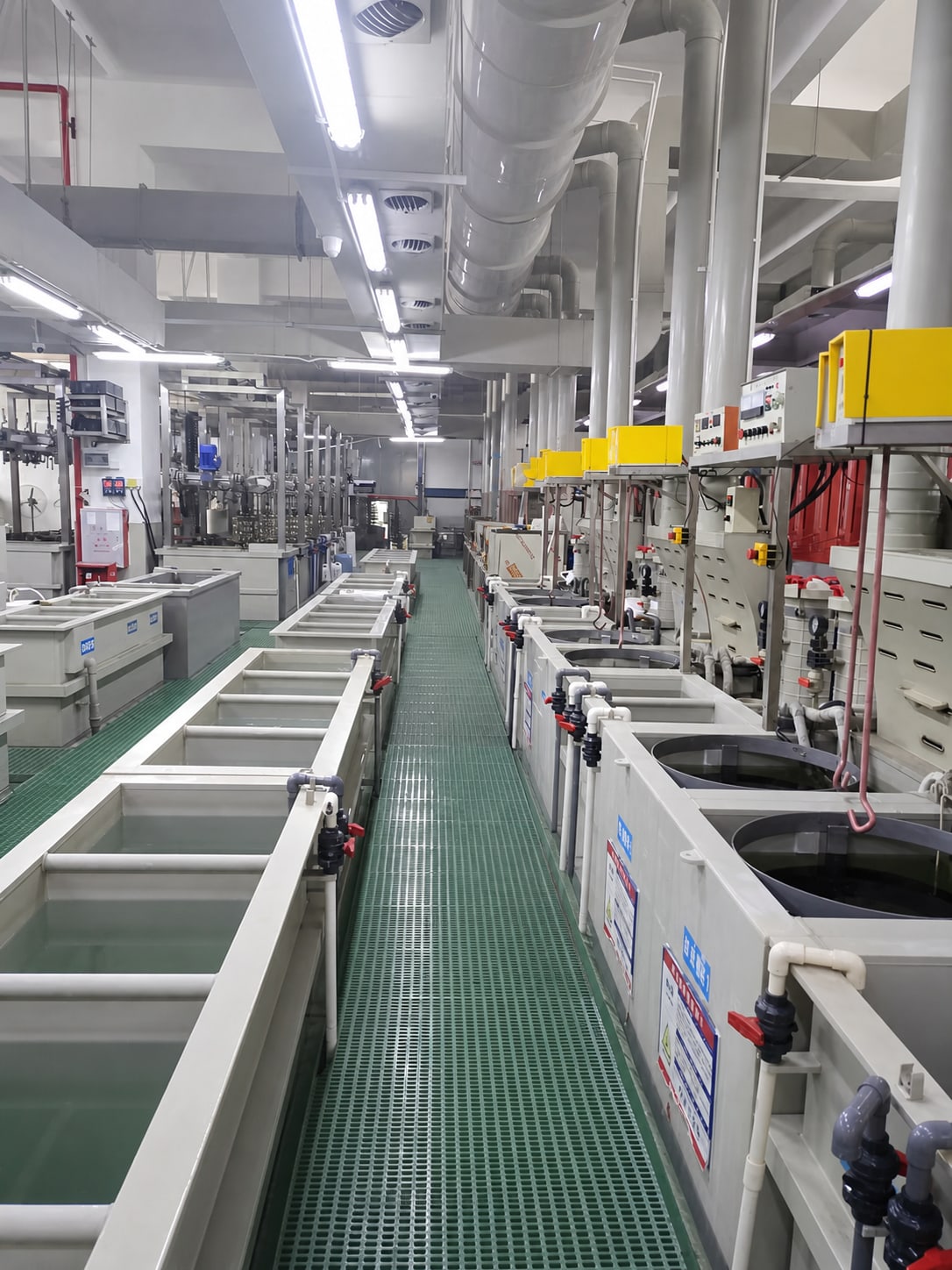
Production capability: visit LIFU Hardware’s electroplating factory for colour development, sampling, automated rack plating and volume-production support.
Specification, preparation and rack points
Section titled “Specification, preparation and rack points”Define the substrate, surface preparation, colour reference, gloss, coverage areas and relevant test requirements. A thin coating does not automatically hide casting flash, porosity, waviness or handling marks on a zinc-alloy part, so tumbling, grinding and polishing should be planned with the final appearance in mind.
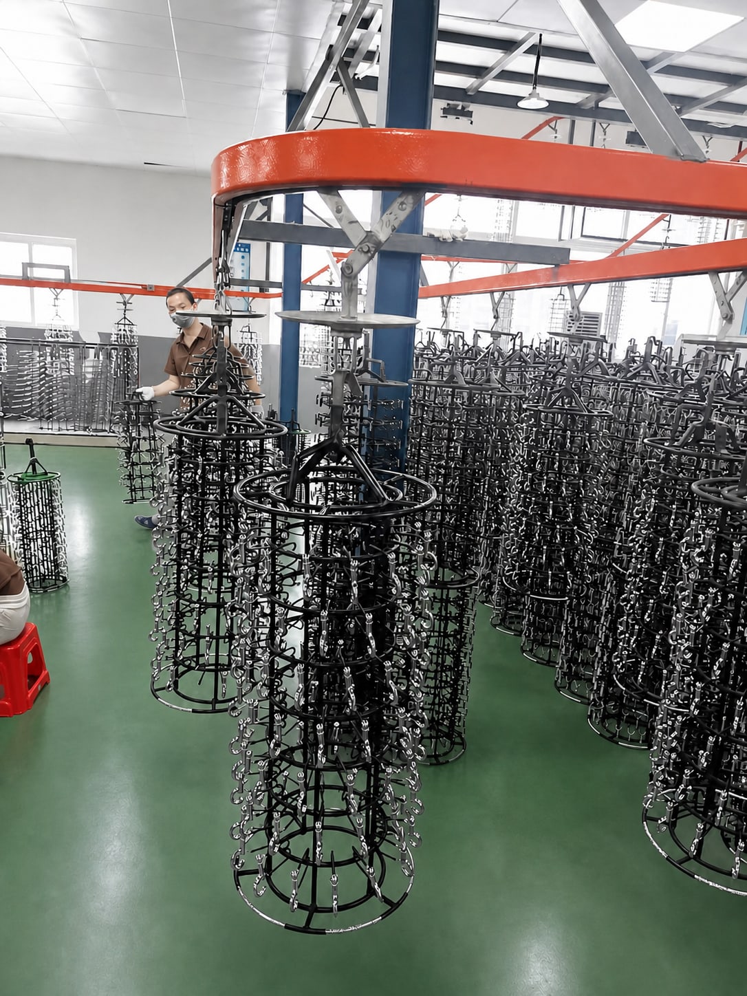
The part also needs a reliable electrical contact and rack location. Rack points affect current distribution and can leave contact marks, so they are normally placed away from critical visible surfaces. Deep recesses, holes, sharp edges and masked areas may coat differently and should be identified during colour and texture development.
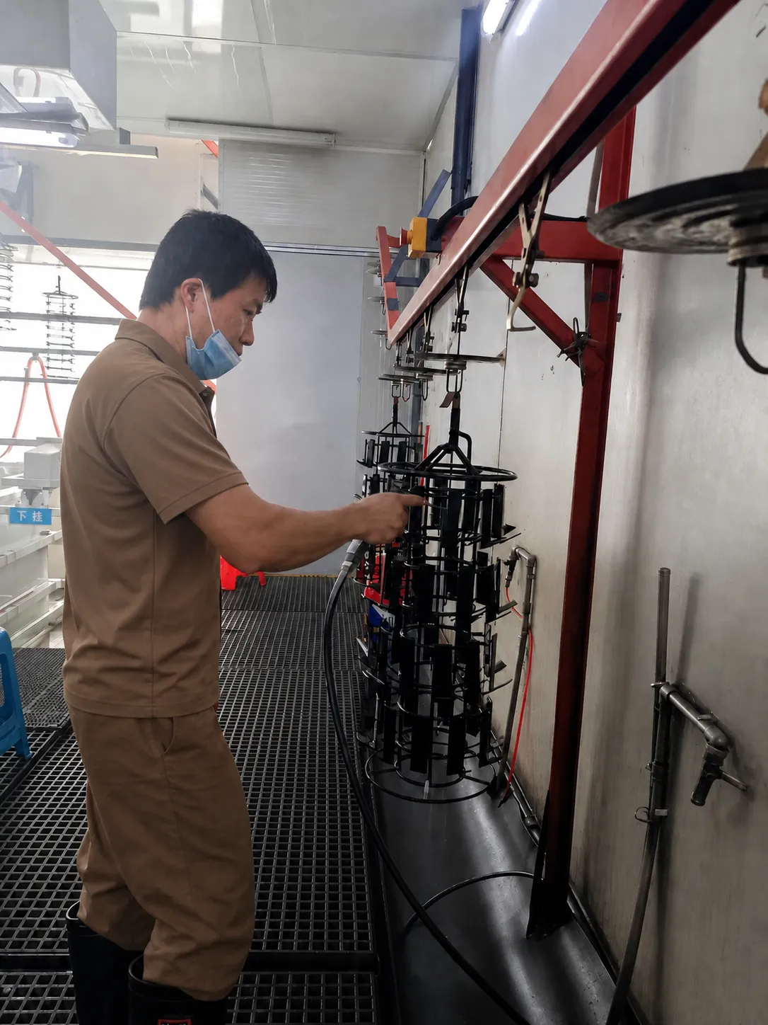
Rack plating, drying and cleaning
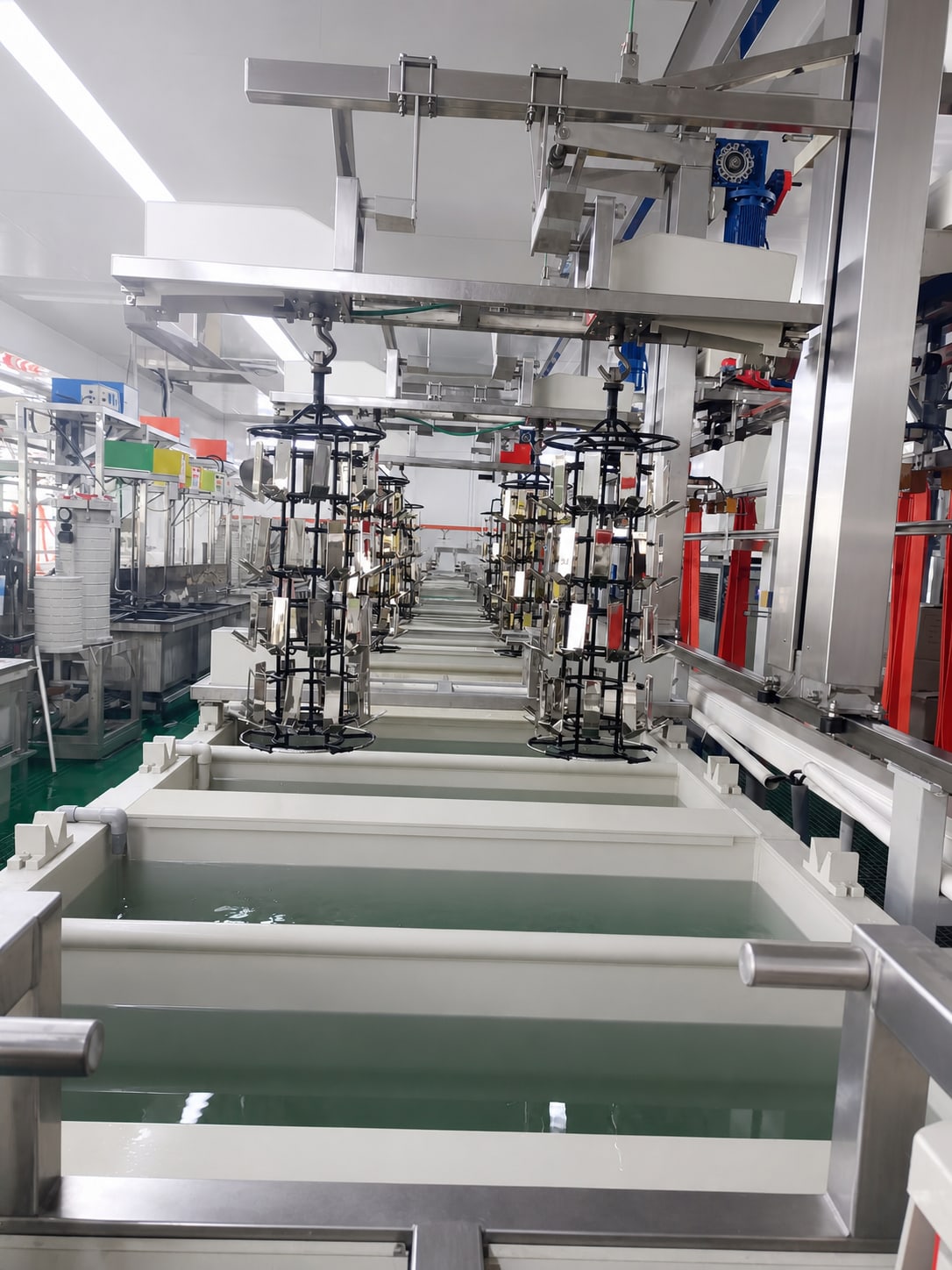
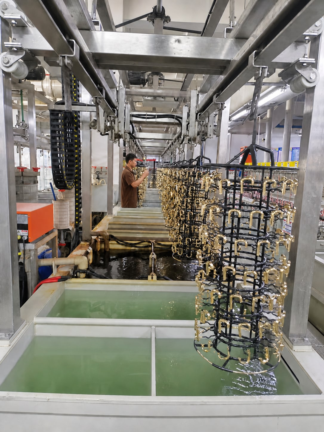
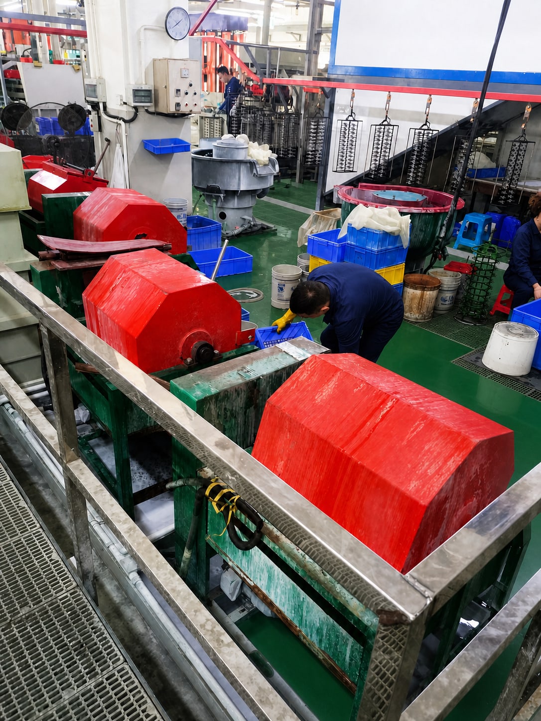
Section titled “Rack plating, drying and cleaning”Rack plating holds parts at controlled contact points as they move through the specified sequence. An automated rack line can provide a consistent route for suitable programmes, while current, chemistry, dwell time, agitation and loading still require process control. After plating, cleaning and drying protect the finish before inspection and packing.
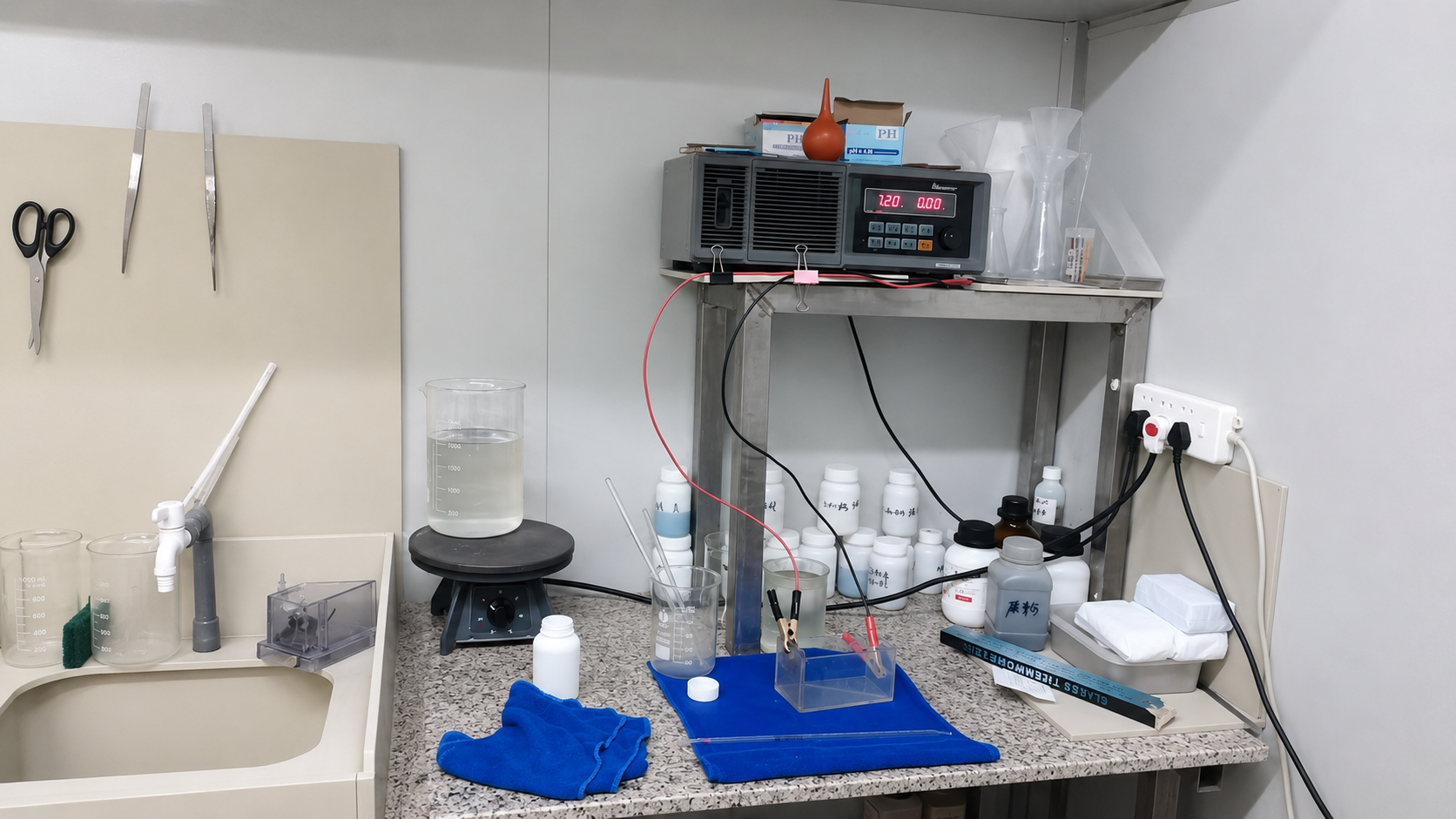
Why the plating bath is checked
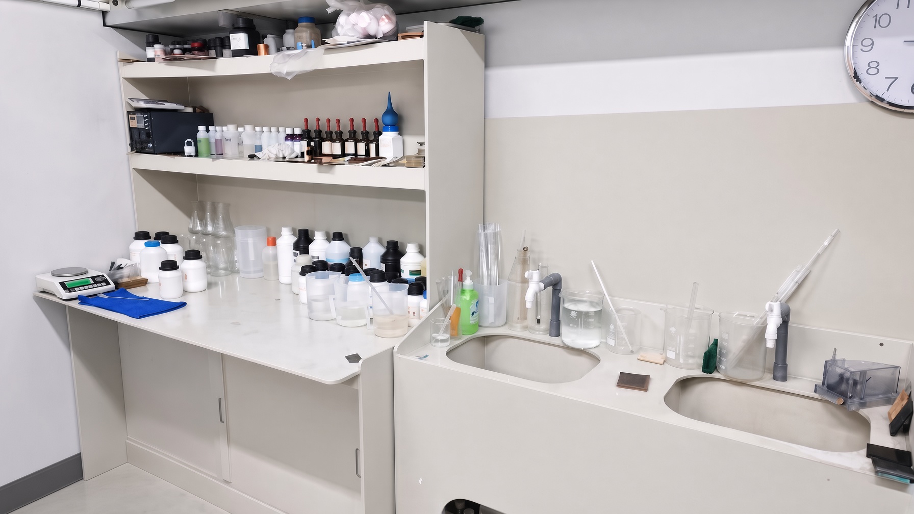
Section titled “Why the plating bath is checked”Bath chemistry changes as parts are processed. The team checks concentration, pH, temperature and metal content, then replenishes it so colour, thickness and coverage stay consistent.
Part loading, current, time, temperature, rinsing and drying also affect the result. If colour or coverage changes, compare the batch with the physical reference sample and check these basic factors before continuing.
| Control point | Why it matters | Useful production evidence |
|---|---|---|
| Solution ratio, concentration and pH | Keeps the chemistry inside its approved operating window | Laboratory test and replenishment record |
| Current, time, temperature and rack loading | Affects deposition rate, coverage and colour | Line setting and batch traveller |
| Rinsing, drying and handling | Reduces staining, residues and handling damage | Route check and inspection record |
| Approved colour sample | Defines the visual target for production | Signed master sample and viewing conditions |
Multi-tone and antique effects
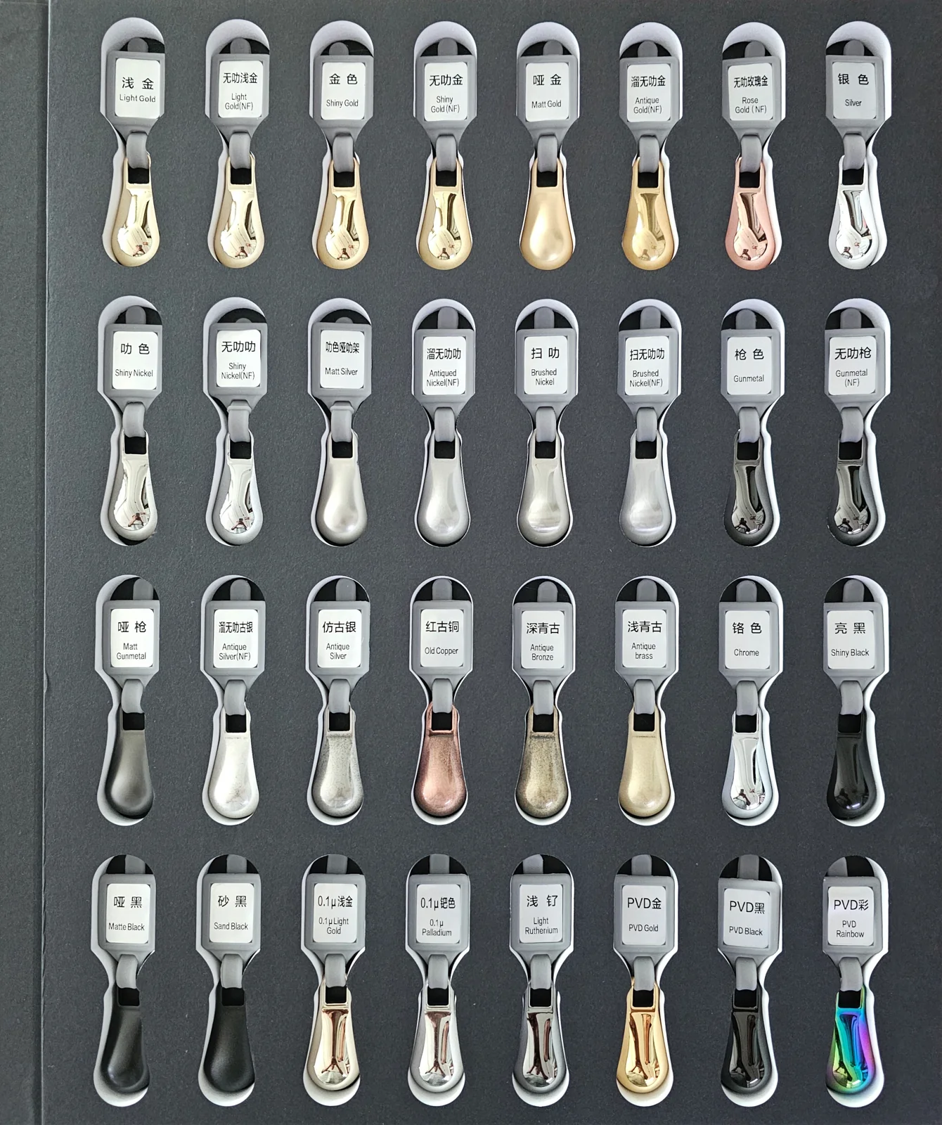
Section titled “Multi-tone and antique effects”Multi-tone and antique appearances are intentional finish effects, not uncontrolled colour variation. They can use a base deposit followed by selective colouring, wiping, darkening or protective steps. Use an approved physical sample to define the intended depth, colour distribution and visible areas.
How to check the finished part
Section titled “How to check the finished part”First compare colour, coverage, pits, burns, exposed base material, adhesion and handling marks with the physical sample. Then select corrosion, adhesion, thickness or chemical-resistance tests that match the intended use; test hours do not translate directly into service life.
| Verification | What it confirms | Planning notes |
|---|---|---|
| Visual and colour comparison | Coverage, approved appearance, rack marks and handling damage | Use the approved physical sample and agreed viewing conditions. |
| Coating-thickness measurement | Deposit meets the approved thickness requirement | Define locations, gauge method and minimum reading quantity. |
| Cross-cut and tape adhesion | Coating remains bonded to the prepared substrate | State the cutting pattern, tape, number of pulls and rating method. |
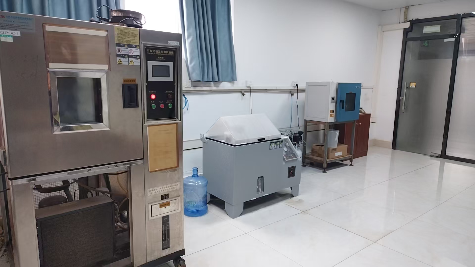
| Humid ageing, including protective-film or leather-contact ageing | Finish stability after controlled heat and humidity exposure | Record the sample condition, checkpoints and acceptable appearance change. |
| Neutral salt spray or CASS (a harsher copper-accelerated salt spray) | Comparative corrosion resistance of the specified system | Select the applicable method, duration and failure definition; do not convert results directly to service life. |
| Alcohol, nitric-acid or other chemical-resistance check | Resistance to a defined handling or contact exposure | Use only an approved method and trained laboratory controls; specify solution, exposure and evaluation. |
Before testing, define the sample condition, rack or cut-edge treatment, exposure duration, inspection interval and acceptance rule. Record whether failure means red or white corrosion, blistering, colour change, loss of adhesion or another agreed defect. A salt spray test can support comparative verification, but the test duration does not replace a complete coating specification and failure definition.
Related terms
Section titled “Related terms”Finish routes · Preparation before coating · Colour control · Salt spray testing · Appearance and adhesion inspection