
Product Development and Sampling
A project can start with a sample authorised for use, a sketch or a reference image. The design team and toolroom help turn the idea into a part that can be manufactured, assembled and inspected. LIFU Hardware can support colour matching and finish development.
The customer-friendly route
Section titled “The customer-friendly route”- Provide the starting information: send a sample, sketch, dimensions, intended use and target appearance.
- Confirm the model: review the 3D form, interfaces, material and visible faces.
- Review an early sample: use a 3D print to assess form, or a CNC metal sample to assess fit, feel and finish direction.
- Choose the tooling: select a dedicated die or, where suitable, a shared holder with replaceable inserts.
- Review the trial: check filling, dimensions, assembly, surface preparation and finish.
- Approve production: finalise the approved sample, inspection points and accessory set before volume production.
The times shown below are typical references, not delivery commitments. Customer feedback, tooling changes, finish trials and non-standard accessories can affect the schedule.
From input to an engineering model
Section titled “From input to an engineering model”A sample demonstrates feel and movement, but does not reveal its exact alloy or hidden dimensions. Add dimensions, thicknesses, radii, fixing points and movement clearances to the sketch. After 3D modelling, check appearance, function and whether tools can reach every surface that requires polishing.
3D printing: see the form early
Section titled “3D printing: see the form early”A resin print allows the customer to check size, curves, grip, holes and initial assembly without making a production die. It does not confirm the final metal part’s weight, strength, surface or plating durability.
CNC metal samples: production-like validation before tooling
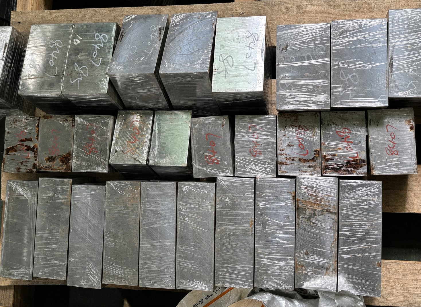
Section titled “CNC metal samples: production-like validation before tooling”A CNC sample is cut from metal stock, so it can provide a representative feel and demonstrate fit, movement and finish direction before a production die is made. A typical reference is 3–7 days, depending on complexity and approvals.
A CNC sample can look close to production, but it does not reproduce casting flow, pores, shrinkage or parting marks. Production die-casting still needs a tooling trial.
Choosing a production die strategy
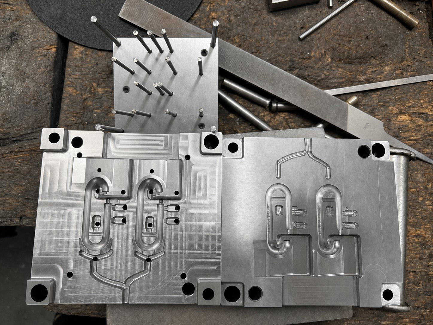
Section titled “Choosing a production die strategy”Die-cast and stamped components normally need production tooling for consistent volume production. A complete dedicated die set allows feed, venting, cooling, slides and ejection to be designed around one product. It suits irregular shapes, intricate patterns or programmes with substantial forecast volume. A typical development reference is 30–40 days. The higher investment must be justified, and a dedicated die does not automatically guarantee the highest precision; product design, toolmaking, machine condition, material and process control all contribute.
A common holder fitted with replaceable cavity, core or insert units retains the standard support frame and changes the product-forming elements. This flexible approach suits some standardised zinc-alloy handbag fittings. A typical reference is 5–10 days. Large parts, complex side actions, special cooling or products incompatible with the available holder may still need a dedicated die.
CNC equipment in the toolroom
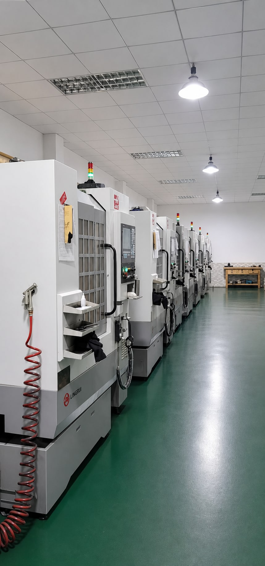
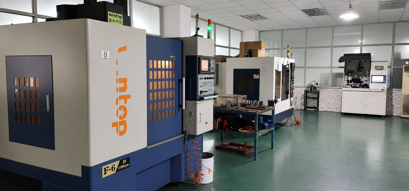
Section titled “CNC equipment in the toolroom”CNC equipment supports the controlled machining needed to make and correct production tooling. The machining path, datum setup and inspection method must follow the approved tool drawing; machine capacity alone does not determine the finished die’s accuracy.
After the tool is complete
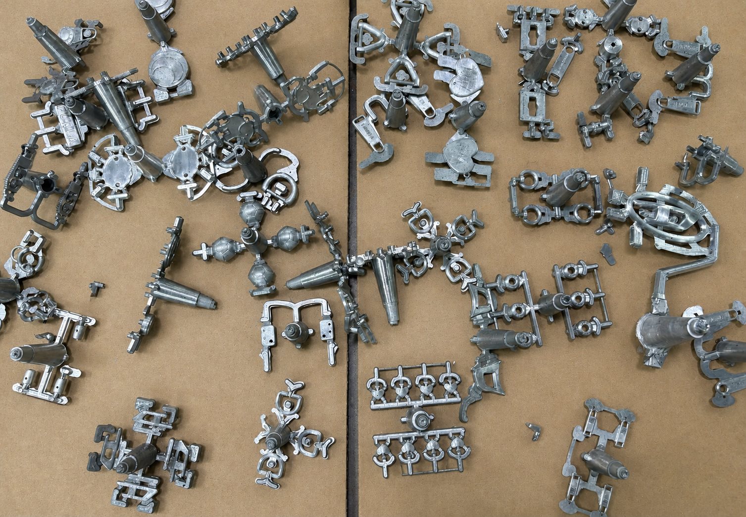
Section titled “After the tool is complete”The first trial checks filling, shrinkage, porosity, flash, distortion, dimensions and ejection. An acceptable casting still requires trimming, deburring, grinding or polishing, cleaning, finishing, assembly and inspection. Moving from an acceptable tool trial to a complete plated or otherwise finished sample typically requires an additional 1–3 days, excluding tool correction, repeated colour trials, special testing or time awaiting approval.
Non-standard screws, rivets, springs, magnets, pins or washers may determine the project schedule. A typical reference for custom small components is 5–7 days, depending on specification, material, finish, fit trials and supply scheduling. Plan around both the main body and the complete accessory set.
Developing a surface effect
Section titled “Developing a surface effect”Bright plating normally starts with a smooth, reflective substrate. Antique or wiped effects build depth through a base colour, selective colouring or removal and a protective layer. Nylon brushing creates directional lines; blasting creates a satin or matt texture. Colour matching should use a physical sample or approved board and record substrate, preparation, layer system, gloss, texture direction and lighting. A photograph alone cannot support a promise of an exact match.
Reading the time references
Section titled “Reading the time references”All times above reflect typical company experience, not fixed delivery commitments. Actual timing depends on the quality and completeness of the starting information, product complexity, production scheduling, material and standard-part availability, trial results, finish approval rounds and customer response. Some work can overlap, but starting tooling or custom accessories before interfaces are finalised increases the risk of rework.
Product development workflow
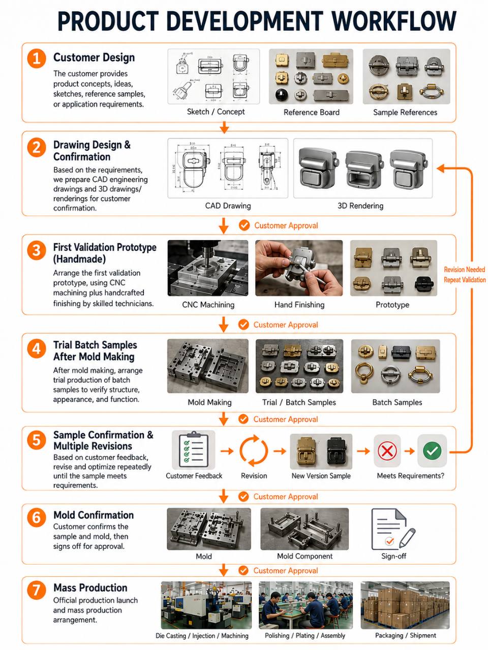
Section titled “Product development workflow”The development route moves from customer input through drawing confirmation, prototype validation, tooling, trial samples and production launch. Customer approval at the appropriate stages keeps the technical definition aligned before the next step begins.
Related terms
Section titled “Related terms”Die casting · Polishing · Electroplating · Hardware structures · Inspection and testing