
Common Hardware Structures
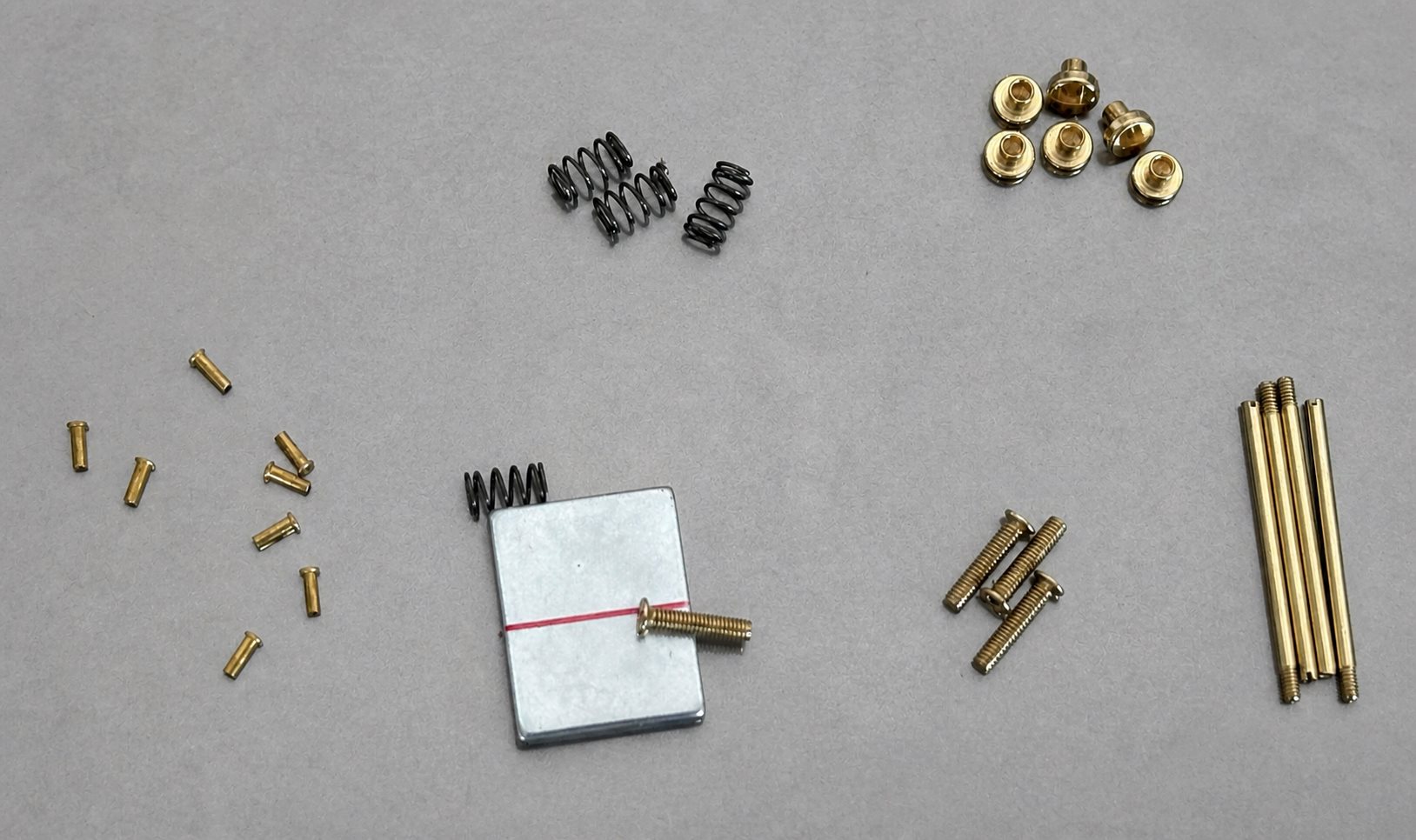
Product names often describe appearance, while the mechanism determines how a part should be designed and inspected. Similar-looking closures may rely on a spring, pin, magnet, friction or screw. Referring only to the product name can obscure the load path, assembly direction and likely failure modes.
Define the function first
Section titled “Define the function first”Is the component connecting, locking, locating, decorating or bearing a load? How does the user open it? Must it operate with one hand, resist accidental release, or provide audible or tactile feedback when closing? Define the mounting material, hole positions, edge distance, permitted projection, movement envelope and visible faces. These inputs guide the development and sampling process.
Spring and pivot mechanisms
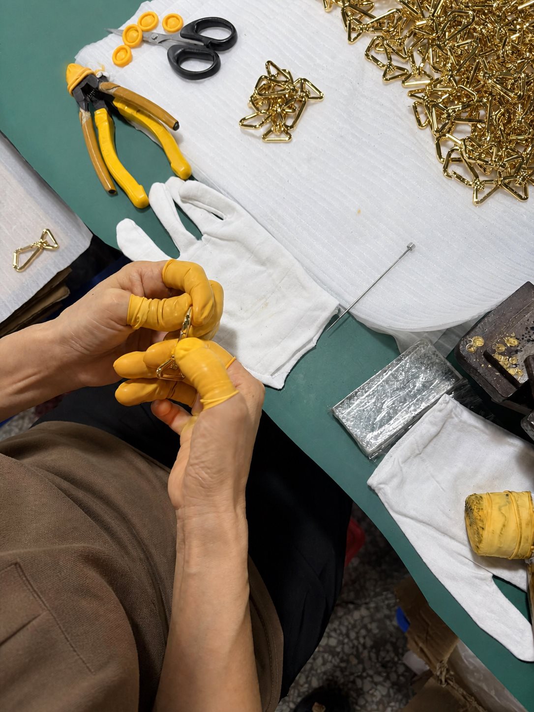
Section titled “Spring and pivot mechanisms”Snap hooks and spring clasps often combine a body, moving gate, pivot and spring. Risks include inadequate opening, slow return, pin migration, permanent spring set and sharp edges at pinch points. Verification should cover operating force, opening, return, repeated cycling and unintended side loads.
Hinges and folding mechanisms use pins, knuckles or riveted positions to control motion. Too little clearance causes binding and finish damage; too much creates play and noise. Plating or PVD changes fit and friction, so a mechanism should not be approved only as an unfinished part.
Magnetic closures and mounting systems
Section titled “Magnetic closures and mounting systems”A magnetic closure combines the magnet and housing with a backing or mating part to form a magnetic circuit. Holding force depends on the magnet grade, gap, orientation, cover thickness and mating steel. Evaluate closing, pull-off, misalignment, drop impact, surface contact and magnet retention—not only the bare magnet.
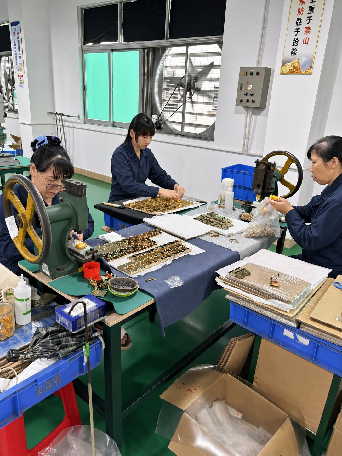
Prongs, screws, rivets and backing plates connect hardware to leather, textile, plastic or metal. Hole geometry, material thickness and installation tooling should be approved together. Excessive setting force can damage the carrier material, while insufficient force can allow the fitting to loosen. Custom small components may also determine the overall sampling schedule.
Finished-product assembly
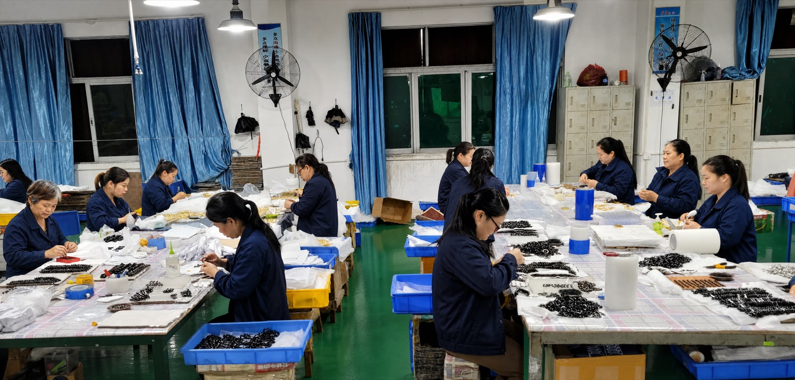
Section titled “Finished-product assembly”Assembly brings the finished body, moving parts, pins, springs, magnets, screws and other components together in their intended working arrangement. Confirm the sequence, tool access, orientation and protection of visible finished faces, then check operation and appearance on the complete product rather than approving each part in isolation.
Materials and process effects
Section titled “Materials and process effects”Zinc alloy supports complex integrated forms, while stainless steel suits thin sections, springs and higher-strength locations. Bodies, pins, springs, magnets and screws may use different materials and finish routes. Review the process by component, then perform functional and quality checks on the complete assembly.
Choosing by movement
Section titled “Choosing by movement”Describe the action clearly: does the part pivot, slide, spring open, hold by magnet or remain fixed? Then show the surrounding assembly. This helps buyers distinguish between a hinge, spring connector, magnetic closure and mounting piece without relying on the name alone.
Easy mix-ups
Section titled “Easy mix-ups”A magnetic hold is not automatically a mechanical lock. A spring gate and a fixed ring can look alike while working differently.
Related terms
Section titled “Related terms”Development and sampling · Zinc alloy · Stainless steel · Inspection and testing